Drilling
Jig for GS-35B Socket Standoffs
(click
the small pictures to see a larger picture in a new browser window)
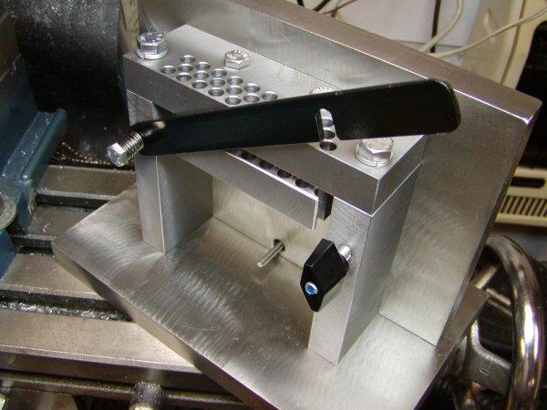
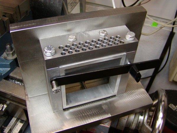 1 Jig with a piece of the aluminum extrusion in place |
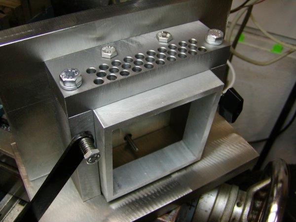 2 The extrusion is almost out of the jig |
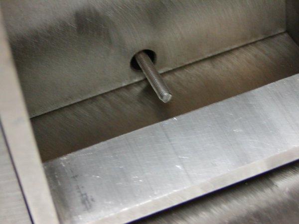 3 This is the bottom depth limit screw. There are two on the sides near the top also. |
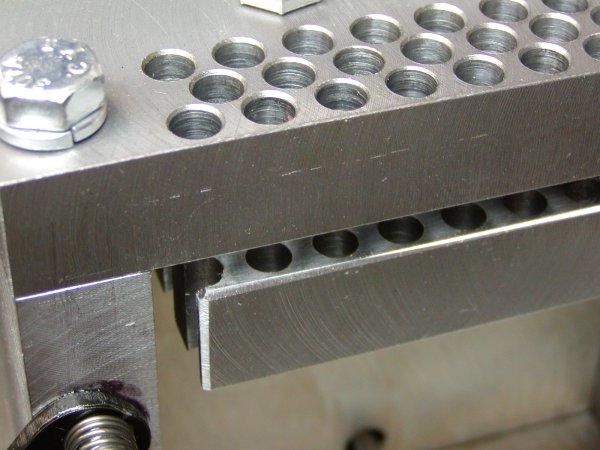 4 You can see the end of the bottom drill plate. Note the end holes are cut through |
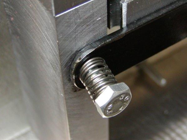 5 The left end of the locking bar is secured with a bolt and spring |
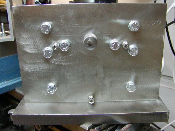
 6 The back of the jig |
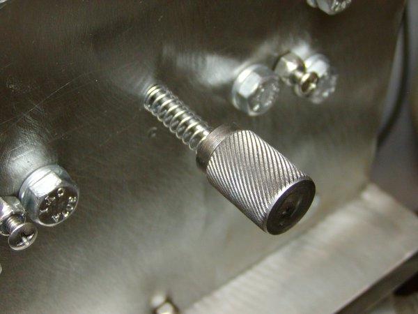 7 I made this ejector pin knob on the lathe. The pin is 1/8" stainless and passes through the knob and is TIG welded. |
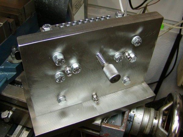
 8 Back side of the jig. The extractor is in the center top. The round phillips head screws are depth limiters. |
 9 The locking bar is raised here |
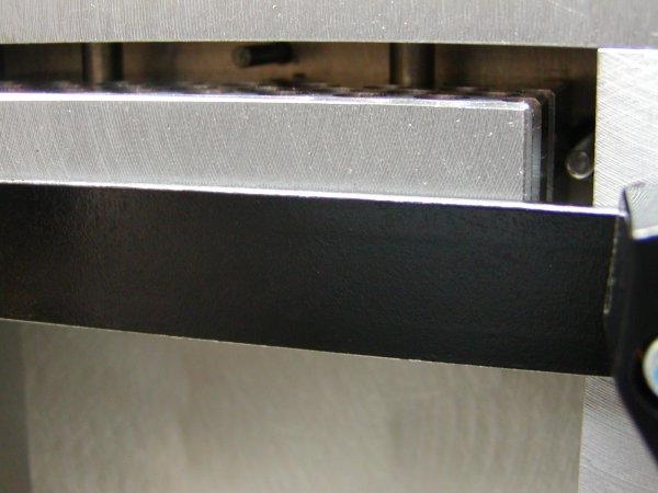 10 Just above the locking bar and inside the crack between the two drill plates you can see the extractor pin, two alignement bolts and on the right vertical one of the depth limiting screws. |
||
|
11 The first drilled piece out of the jig. |
12 Back side of the drilled piece. No cleanup has been done. This will take minimum cleanup. |
13 The extractor rod hit this tapped hole. Since this photo was taken I added a foot on the extractor rod. |
-
|