"Antenna Matching Unit
Adjustment
The Antenna Matching Unit is used only in continuous duty duplex stations
to optimize impedance matching between the power amplifier and the load.
It consists of a Pi network (C2-C5 and L1) and a reverse directional coupler.
RF from the low pass filter is applied to the Pi network through the reverse
directional coupler and then to the duplexer load. The reverse directional
coupler permits monitoring the reflected power.
1. Connect DC Voltmeter across TP1 and ground.
2. Tune C2 and C4 for minimum voltage as indicated on DC Voltmeter.
3. Push L1 toward or away from the filter cover wall to further reduce the DC voltage.
4. Repeat steps 2 and 3 as necessary to obtain an absolute minimum voltage reading.
Note: The residual voltage reading after tuning may vary from one transmitter to the next depending on output power level, operating frequency, and load".
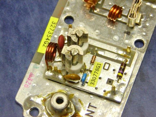 |
VHF Z-Match |
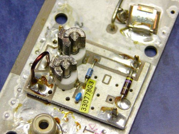 |
UHF Z-Match |
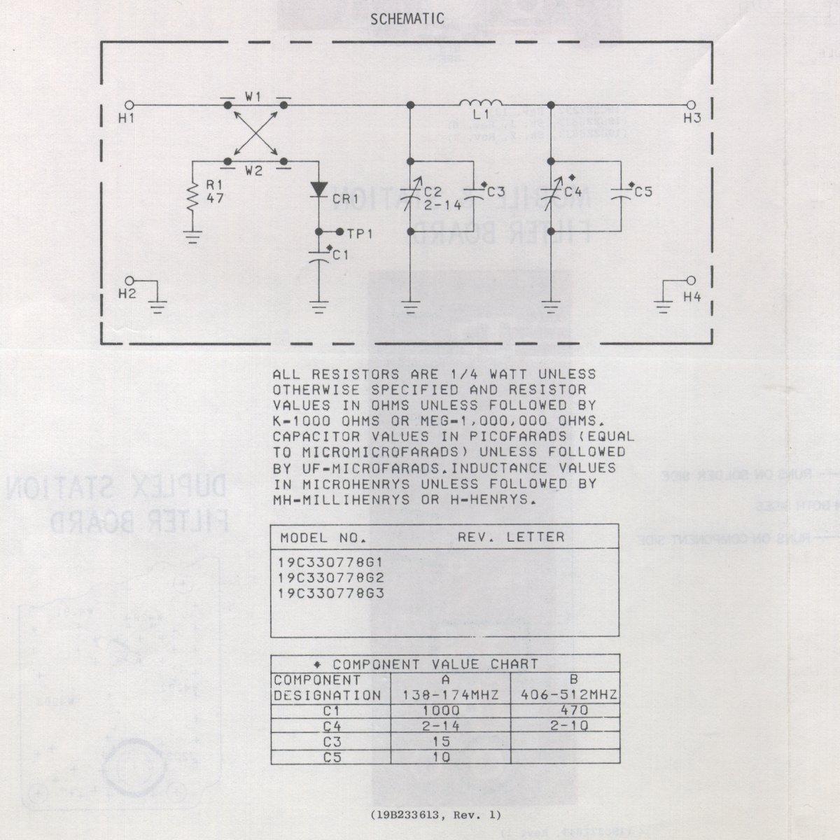 |
Z-Match Schematic. Caution, this opens a large .jpg |
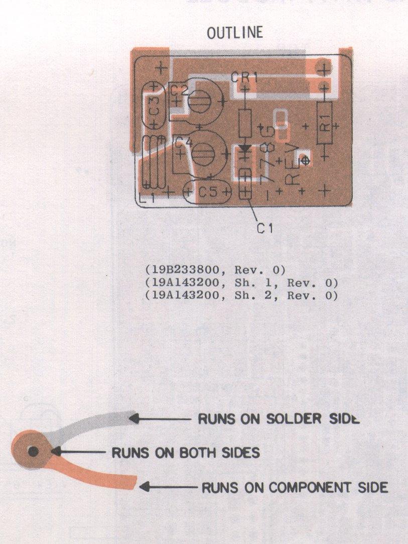 |
Z-Match Board layout. Caution, this opens a large .jpg |
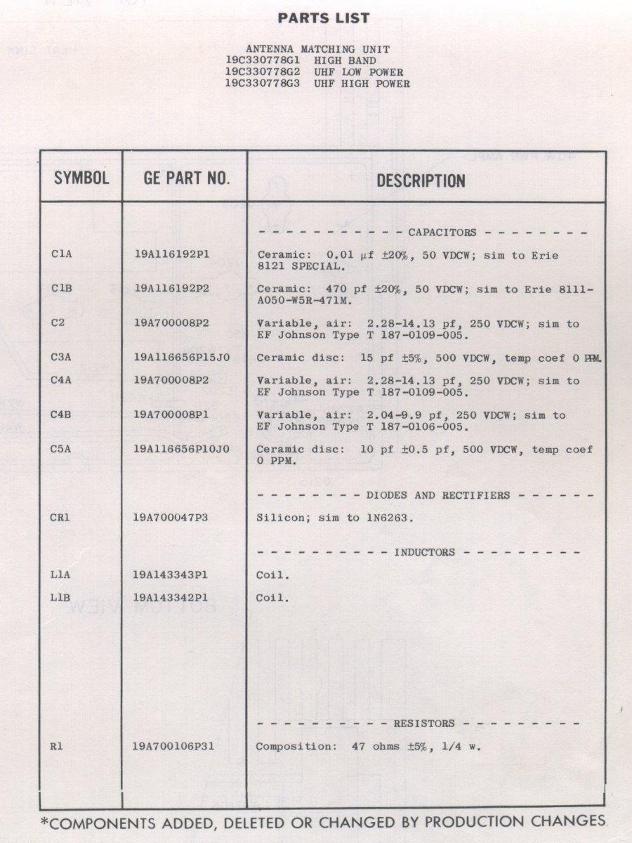 |
Z-Match parts list. Caution, this opens a large .jpg |