|
W4ZT
UHF Repeater
|
Union
City, Georgia
442.125
MHz (+5 MHz) tone required 100 Hz
UHF
Repeater Controller
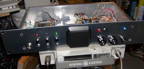
Contains an integrated control head for the GE MastrII UHF radio, a CAT-250 controller board and a prototype board with interface circuits. The repeater radio is now a continuous duty duplex shelf unit instead of the mobile shown below.
Contains an integrated control head for the GE MastrII UHF radio, a CAT-250 controller board and a prototype board with interface circuits. The repeater radio is now a continuous duty duplex shelf unit instead of the mobile shown below.
(click
the small pictures to see a larger picture in a new browser window)
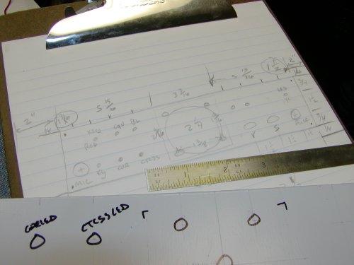 |
It started with a diagram on paper. |
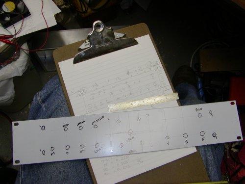 |
The front panel layout about ready to drill. |
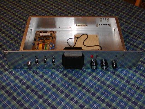 |
After drilling all the holes then mounting parts makes it look like something. |
| Face of the controller before wiring. | |
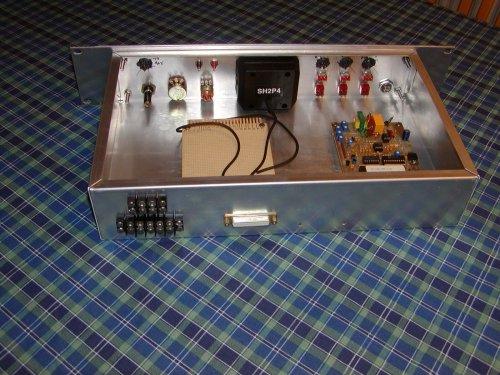 |
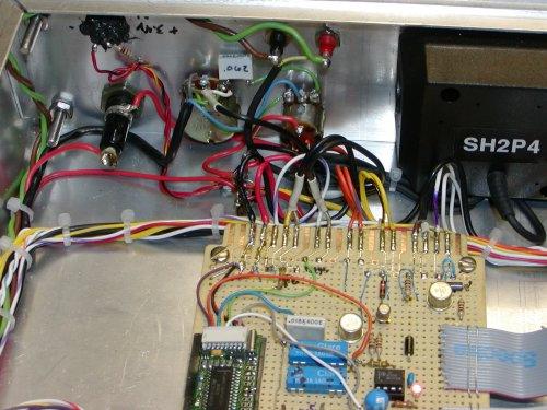
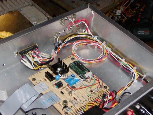
Inside view. The RC-1000 controller board has been replaced by a CAT-250 controller board. A prototype board on your left for various interface needs. It has also been rebuilt. |
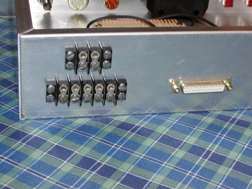 |
Connectors on the back for 12 volts DC, telephone and the cable to the GE MastrII (on the DB25 connector). |
 |
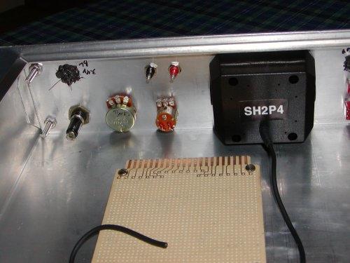
Switches, LEDs and a microphone connector on one side... |
 |
Fuse, LED, squelch, volume and speaker test points on the other. |
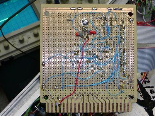 |
Bottom of the interface board. All prototype. The 5 volt regulator is center top. |
 |
Wiring of the fuse holder, squelch and volume controls and interface board. |
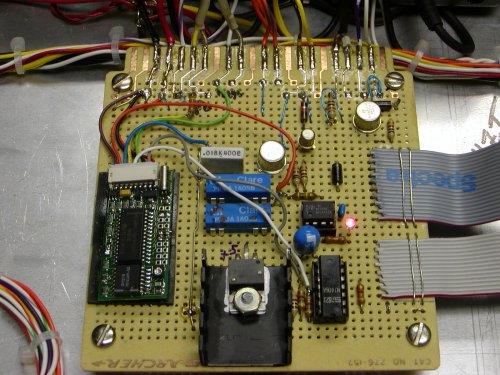 |
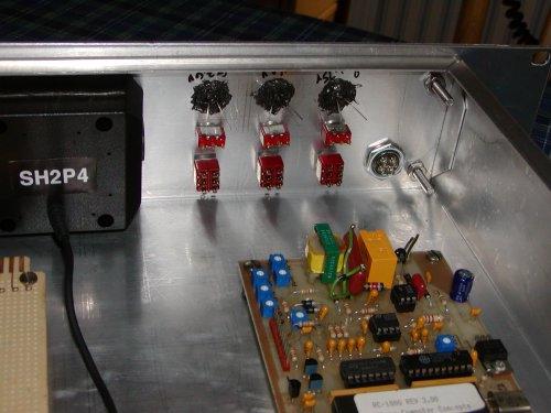
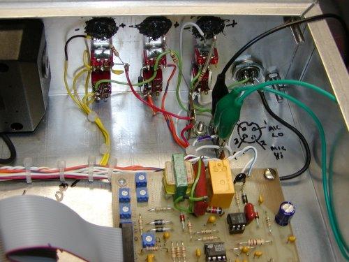
Top side of the interface board. The TS-64 CTCSS encoder/decoder is on the left. The 5 volt regulator is bottom center. Above the regulator are two blue relays, one for fan control and one for PTT into this board. The new interface board makes proper connections to the CAT-250 controller. It still contains the TS-64 etc. |
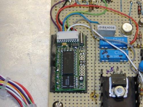 |
Here is the TS-64. |
 |
Wiring of the control switches, LEDs and microphone connector. |
 |
The interface board and rear connectors. |
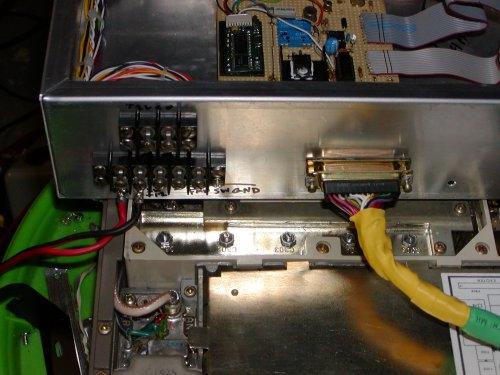 |
The rear panel barrier strips and connector for the control cable. |
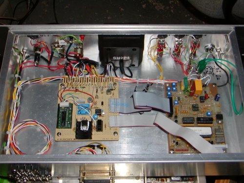 |
Looking down into the chassis. |
| Front panel with lights. | |